Intro Link to heading
You can find the source code for the board in this Gitlab Repo
This guide is intended for tinkerers/professionals learning the basics of Zephyr. It assumes you have some understanding of what an RTOS is, basic electronics (you should know what a transistor does), and some experience with zephyr, at least completing the Zephyr Getting Started Guide. It will go over pertinent information as needed, such as device tree basics, schematic meanings, and reading pin multiplexing in datasheets. This guide will be a more interactive approach to the Zephyr Board Porting Guide. I recommend once you’re done with this, read through that guide thoroughly.
🔵The scope of this guide is to get blinky running on an out-of-tree board. It aims to be rather simple but provide a good foundation to further add other hardware and software support
Development board Link to heading
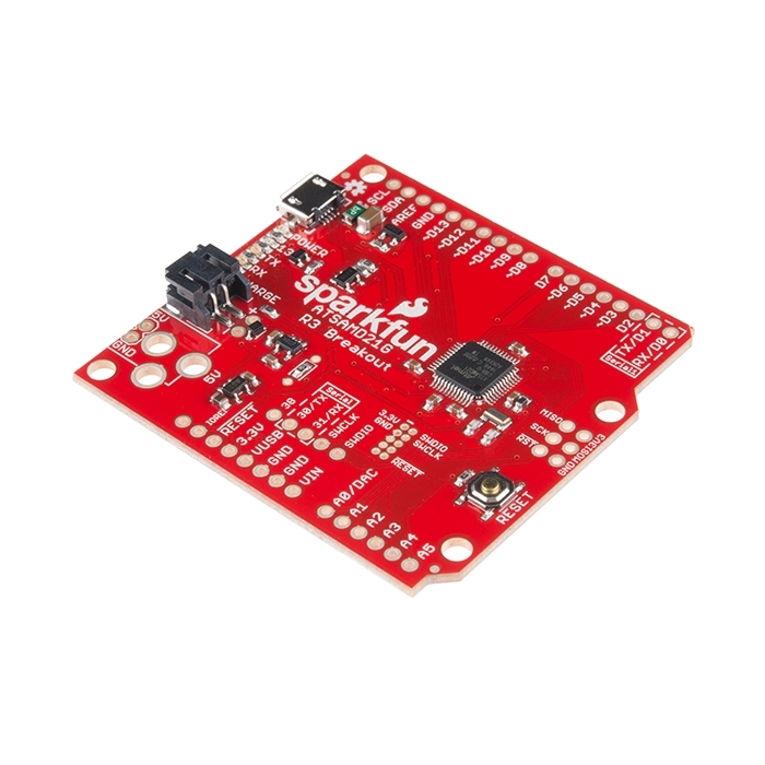
I’ll be porting a SAMD21 Dev Breakout SoC
Here’s my rational for chosing this board:
- Affordable (~$30)
- Well Documented
- Arduino compatible, familiar and usable in the Arduino IDE if you want to go that route.
- Not in Zephyr yet, opportunity to contribute.
- The SoC it’s based on (ATSAMD21G) is supported in Zephyr, and also an awesome chip.
ATSAMD21G SoC Link to heading
The ATSAMD21G is awesome for a lot of reasons itself. It’s a modern MCU focusing on flexibility and simplicity. It’s based on the Cortex M0+; There is no Security Abstraction Unit (SAU), Memory Protection Unit (MPU), and no caches for instructions or data (the Wikipedia Page for the Cortex series of CPU’s is a comprehensive summary if you’re curious). For a beginner familiar with arduino looking to get more power in a similiar form factor, the ATSAMD21G is an excellent transition (even if you don’t want to learn Zephyr, you can get a arduino supported board and just use the Arduino IDE).
Besides it’s simplicity, the ATSAMD21G SoC is very flexible for creating modern firmware applications. The magic is in it’s 52 programmable i/o pins. While these pins can be configured as GPIO, the SoC also provides 6 Configurable Serial Communication Modules (SERCOM), supporting I2C (including SMBus),SPI,UART/USART, and LIN slave. Off the cuff I feel 90% of sensors and actuators use I2C and SPI and almost always use UART. The chip supports a bunch of other types of protocols and interfaces but we will focus just on I2C, SPI, UART, and GPIO. Check the datasheet for everything it supports (Such as the incredibly cool I2S protocol).
Resources Link to heading
Website Pinout Schematic Datasheet
Step-by-Step Link to heading
I’m approaching this from a “bottom-up” perspective. I feel that it’s overwhelming to take in the blackbox architectural information without much context to it’s underlying structure.
First copy the blinky example to your own directory to modify:
Prerequisites Link to heading
🔴 Ensure that you have the zephyr build environment, if not read the Zephyr Getting Started Guide. This assumes you followed the directory structure from that guide.
🟡 Beginner Note I use neovim for my text editor. When you see me using nvim to edit files below, feel free to swap it for whatever you like: Including nano, vim, emacs, gedit, or whatever (I recommend nano, there is no GUI and and it’s included in many linux distros by default).
Setting up basic board structure for Zephyr Link to heading
cp -r ~/zephyrproject/zephyr/samples/basic/blinky ~/sparkfun_samd21_blinky
# -r is short for --recursive
Alright, now before we can compile we have to define our board first. Let’s start by creating our board directory in the zephyr repository. The guide states we should put it in zephyr/boards/<VENDOR>/<BOARD>. Our vendor is the existing directory sparkfun, and we get to choose the name for our board, which will be samd21_dev_breakout.
mkdir -p ~/zephyrproject/zephyr/boards/sparkfun/samd21_dev_breakout
# -p is short for --parents
Now in this directory, we can begin to add the files required to define our board. First, create and edit the file, board.yml:
cd ~/zephyrproject/zephyr/boards/sparkfun/samd21_dev_breakout
touch board.yml
nvim board.yml
# board.yml file
board:
  name: sparkfun_samd21_breakout
  full_name: Sparkfun SAMD21 Dev Breakout
  vendor: sparkfun
  socs:
    - name: samd21g18a
Verify that west can identify the new board:
Run this to find all boards that have sparkfun in the title
west boards -n sparkfun
# -n is short for --name
You should see the new board ==sparkfun_samd21_breakout== among other boards.
# west boards -n sparkfun output
sparkfun_thing_plus
sparkfun_pro_micro_rp2040
sparkfun_red_v_things_plus
sparkfun_thing_plus_matter_mgm240p
sparkfun_samd21_breakout # The new board
Configuring board for blinky example Link to heading
Great, now lets try to build the blinky sample with our new board
cd ~/zephyr/zephyrproject
west build -p always -b sparkfun_samd21_breakout samples/basic/blinky
When building it we see this error:
...
CMake Error at /home/ricf/zephyrproject/zephyr/cmake/modules/arch_v2.cmake:36 (message):
  ARCH not defined.  Check that BOARD=sparkfun_samd21_breakout, is selecting
  an appropriate SoC in Kconfig, SoC=, and that the SoC is selecting the
  correct architecture.
...
Let’s fix that by making a Kconfig and selecting an appropriate SOC. Go into the new board directory and create and edit the file: Kconfig.sparkfun_samd21_breakout and select the SOC for the devboard: SOC_SAMD21G18A.
cd ~/zephyrproject/zephyr/boards/sparkfun/samd21_dev_breakout
touch Kconfig.sparkfun_samd21_breakout
nvim Kconfig.sparkfun_samd21_breakout
# Kconfig.sparkfun_samd21_breakout
config BOARD_SPARKFUN_SAMD21_BREAKOUT
        select SOC_SAMD21G18A
Let’s see if the addition of this Kconfig file fixed that error and exposed new ones. Run the west build command:
cd ~/zephyr/zephyrproject
west build -p always -b sparkfun_samd21_breakout samples/basic/blinky
Adding a device tree Link to heading
🔵The syntax of device tree’s wont be covered here, that is beyond the scope of this guide. Copy/Paste will be enough for now and the structure should make enough intuitive sense for this guide.
This time, we see that, among other issues, there’s an error saying we have a bad definition for the clock speed:
#error "SYS_CLOCK_HW_CYCLES_PER_SEC must be non-zero!"
This makes sense, the processor doesn’t know what it’s speed should be, that is board specific. Some SAMD21G18A based SOCs could use a variety of clock speeds, we need to let zephyr know what frequencies we want to use.
To define the clock speed (and other hardware configurations) for our board we need to first create and edit a device tree (or dts) file. Without going into too much detail, the device tree maps physical pins to mnemonic variables. Quick example, to toggle an LED you may be used to coding something along the lines:
function blink() {
	pin_1 = on;
	sleep 1;
	pin_1 = off
	sleep 1;
}
This could work for one particular board, but it isn’t clear what pin_1 is exactly, nor would this work for other boards that have separate functionality and location of it’s own pin_1. The device tree both defines the purpose of the physical pin, and configures it outside of the code. So instead of hardcoding pin_1 , the device tree could expose a variable for the pin with something like, LED_PIN. You would set that pin in the device tree and the code would get the pin from that name. So if you switch to another board, you wouldn’t need to change anything besides the device tree entry for that pin. Of course this is much more complicated in practice, but that should be enough context for now. The official documentation is there if you want to understand it in more detail. For now, let’s start by making our dts file:
First create and start editing a dts file named sparkfun_samd21_breakout.dts
cd ~/zephyrproject/zephyr/boards/sparkfun/samd21_dev_breakout
touch sparkfun_samd21_breakout.dts
nvim sparkfun_samd21_breakout.dts
To fix our error #error "SYS_CLOCK_HW_CYCLES_PER_SEC must be non-zero!", we simply need to define the clock frequency our board operates at. Reading page 3 of the manual we can see that the clock frequency is 48KHz. To set this, edit your sparkfun_samd21_breakout.dts file as below:
/dts-v1/;
#include <atmel/samd21.dtsi>
#include <atmel/samx2xx18.dtsi>

&cpu0 {
        clock-frequency = <48000000>;
};
If all is going well, the previous error should be gone and we can give our attention to new ones. When trying to rebuild with the west build command you should see an error similar to this:
/workdir/zephyr/include/zephyr/device.h:96:41: error: '__device_dts_ord_DT_N_ALIAS_led0_P_gpios_IDX_0_PH_ORD' undeclared here (not in a function)
   96 | #define DEVICE_NAME_GET(dev_id) _CONCAT(__device_, dev_id)
      |                                         ^~~~~~~~~
It’s a bit hard to understand the source of this error without context. The undeclared string __device_dts_ord_DT_N_ALIAS_led0_P_gpios_IDX_0_PH_ORD is part of the device tree preprocessor. Basically, it’s failing to find the device tree alias associated with this macro from the blinky source #define LED0_NODE DT_ALIAS(led0). That is, led0 is undeclared in our device tree. Let’s go ahead and fix that.
Adding Hardware to Device Tree Link to heading
Identifying the correct pin Link to heading
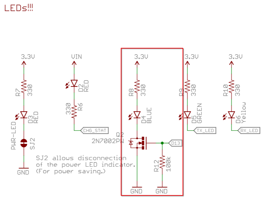
Most dev boards (this one included) have an onboard LED connected to an easily accessed GPIO for debugging. It’s perfect for our situation and is almost a standard in developing for MCUs. Let’s look at the schematic. Looking at the beautifully labeled LEDs!!! section, we can see there are LEDs for power, charger status, tx indicator, rx indicator, and (labelled in the red box) a user LED. This LED is connected to the drain of a n-channel MOSFET transistor. The gate of the transistor is connected to pin D13 and is pulled low via the 100k resistor to GND. If you understand, great, if not, don’t worry all you need to know is turning pin D13 on turns the LED D4 on, and when pin D13 is off then LED D4 is also off. We refer to this configuration as active high , since the LED is on or “active” when the pin is “high”. If turning the pin on turned the LED off it would be active low.
🟡 I’m italicizing pin and LED for D13 and D4 respectively. This is because it’s confusing that the pins and LEDs are both prefixed with D. For the pin it’s to signify digital (as opposed to analog), for the LED it’s to signify Diode, and for us, it’s there to confuse us!
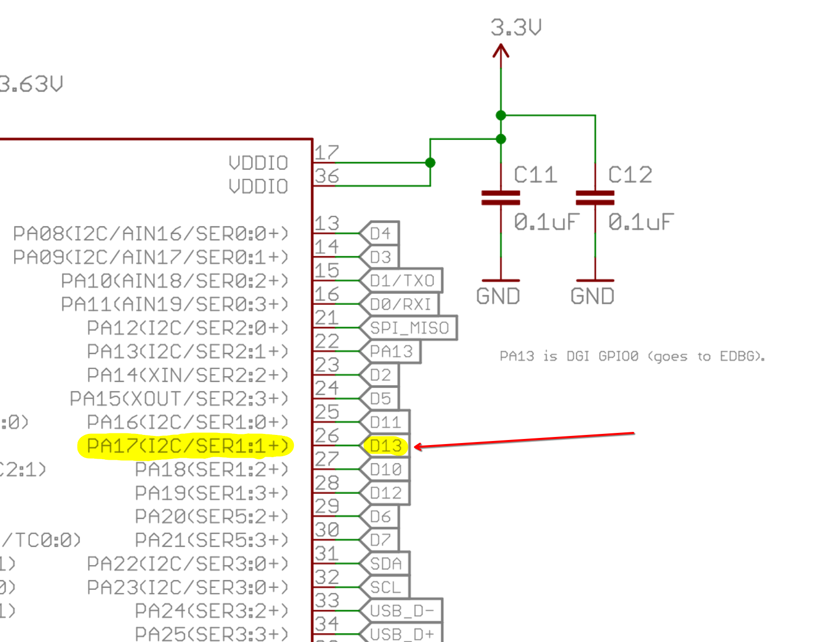
We can trace the D13 pin back to it’s location on the MCU itself. From the schematic we can see that the pin labelled D13, goes to pin 26 on the MCU and it is labelled, “PA17(I2C/SER1:1+)”. We can ignore what’s in the parenthesis for now, this is for alternative SERCOM configurations we are not using. The information we care about: D13(LED control pin) -> PA17. PA17 means port A, pin 17. There’s two ports on a SAMD21: Port A and Port B. Each port has 32 configurable pins. We will get into that configuration later, but for now just understand that a pin you see on the board itself routes back to a Port and Pin combo.
So lets try to bring all this together. Once over for brevity…
- Our compiler is encountering errors because we don’t have the alias
led0defined in our device tree, so it doesn’t know which pin to toggle for blinky. - We identified that the pin labelled D13 controls the LED and is connected to PORT A, PIN 17 or shortened to PA17.
- The configuration of the pin requires that it is Active High so that turning the pin “on” will turn the LED “on”.
Based on these observations the resulting device tree should look something like this (including our previous clock-frequency addition):
/dts-v1/;
#include <atmel/samd21.dtsi>
#include <atmel/samx2xx18.dtsi>

/ {
    leds {
        compatible = "gpio-leds";
        led: led_0 {
            gpios = <&porta 17 GPIO_ACTIVE_HIGH>; // d13
            label = "LED";
        };
    };

    /* These aliases are provided for compatibility with samples */
    aliases {
            led0 = &led;
    };
};

&cpu0 {
        clock-frequency = <48000000>;
};
There’s a lot to unpack with device trees, so don’t worry too much on parts you don’t understand (like funny syntax and this compatible keyword). For now just take away this.
- We have defined our LED pin from our requirements and named it simply ’led':
led: led_0 {
    gpios = <&porta 17 GPIO_ACTIVE_HIGH>; // d13
    label = "LED";
};
- We define the alias we are looking for (
led0) below that definition:
aliases {
    led0 = &led;
};
So now zephyr should know the information required to toggle the pin as it can map where to go from our entry.
Defining Memory Regions Link to heading
If you try to build again with the west build command you’ll get some more nasty errors:
/workdir/zephyr-sdk-0.17.0/arm-zephyr-eabi/bin/../lib/gcc/arm-zephyr-eabi/12.2.0/../../../../arm-zephyr-eabi/bin/ld.bfd: zephyr/zephyr_pre0.elf section `rom_start' will not fit in region `FLASH'
/workdir/zephyr-sdk-0.17.0/arm-zephyr-eabi/bin/../lib/gcc/arm-zephyr-eabi/12.2.0/../../../../arm-zephyr-eabi/bin/ld.bfd: zephyr/zephyr_pre0.elf section `datas' will not fit in region `RAM'
/workdir/zephyr-sdk-0.17.0/arm-zephyr-eabi/bin/../lib/gcc/arm-zephyr-eabi/12.2.0/../../../../arm-zephyr-eabi/bin/ld.bfd: region `FLASH' overflowed by 9738 bytes
/workdir/zephyr-sdk-0.17.0/arm-zephyr-eabi/bin/../lib/gcc/arm-zephyr-eabi/12.2.0/../../../../arm-zephyr-eabi/bin/ld.bfd: region `RAM' overflowed by 3896 byte
Whats happening here is the linker is trying to create our executable .elf file, but it doesn’t know where RAM or FLASH memory is located. This once again needs to be described in the dts file. The RAM is the easy part, as the memory location of SRAM is already included in the SOC definition we include. So we just have to point it to the correct variable sram0:
// sparkfun_samd21_breakout.dts
...
	chosen {
		zephyr,sram = &sram0;
	};
...
Flash is a bit more complicated… We know where flash is (You can verify in the datasheet but all SAMD21G18A MCU’s have the same Flash and SRAM locations), but we need to define it’s layout. This is not unlike regular disk partitions if you are familiar. Luckily though we have a trick up our sleeves called ctrl-c and ctrl-v. It turns out that a lot of devices use the same MCU (SAMD21), so… let’s just take it from another dts file, in this case I’ve just copied the seeediuno dts entry for flash. Different use-cases require different memory layouts, but this one is applicable for most applications:
// sparkfun_samd21_breakout.dts
...
	chosen {
		zephyr,sram = &sram0;
        zephyr,flash = &flash0;
        zephyr,code-partition = &code_partition;
	};
...
&flash0 {
	partitions {
		compatible = "fixed-partitions";
		#address-cells = <1>;
		#size-cells = <1>;

		boot_partition: partition@0 {
			label = "uf2";
			reg = <0x00000000 DT_SIZE_K(8)>;
			read-only;
		};

		code_partition: partition@2000 {
			label = "code";
			reg = <0x2000 DT_SIZE_K(256-8-16)>;
			read-only;
		};

		/*
		 * The final 16 KiB is reserved for the application.
		 * Storage partition may be used by FCB or LittleFS.
		 */
		storage_partition: partition@3c000 {
			label = "storage";
			reg = <0x0003c000 DT_SIZE_K(16)>;
		};
	};
};
To make this a bit easier to parse, our memory layout ends up looking like this:
Flash Memory Map (total ~256 KiB)
+---------------------------------------------------------------+
| Offset      | Partition         | Size         | Description  |
+-------------+-------------------+--------------+--------------+
| 0x00000000  | boot_partition    |    8 KiB     | UF2 boot     |
|             |                   |              | read-only    |
+-------------+-------------------+--------------+--------------+
| 0x00002000  | code_partition    | 232 KiB      | Application  |
|             |                   |              | read-only    |
+-------------+-------------------+--------------+--------------+
| 0x0003C000  | storage_partition |   16 KiB     | FCB/LittleFS |
|             |                   |              | storage area |
+-------------+-------------------+--------------+--------------+

Legend:
- boot_partition: used for bootloader/UF2; occupies first 8 KiB
- code_partition: follows boot; takes up (256 - 8 - 16) = 232 KiB
- storage_partition: final 16 KiB reserved for application data, filesystem, or FCB
Giving us our final DTS file…
Giving us our final DTS file...

```dts
/dts-v1/;
#include <atmel/samd21.dtsi>
#include <atmel/samx2xx18.dtsi>

/ {
    chosen {
        zephyr,sram = &sram0;
        zephyr,flash = &flash0;
        zephyr,code-partition = &code_partition;
    };

    leds {
        compatible = "gpio-leds";
        led: led_0 {
            gpios = <&porta 17 GPIO_ACTIVE_HIGH>; // d13
            label = "LED";
        };
    };

    /* These aliases are provided for compatibility with samples */
    aliases {
        led0 = &led;
    };
};

&cpu0 {
    clock-frequency = <48000000>;
};

&flash0 {
    partitions {
        compatible = "fixed-partitions";
        #address-cells = <1>;
        #size-cells = <1>;

        boot_partition: partition@0 {
            label = "uf2";
            reg = <0x00000000 DT_SIZE_K(8)>;
            read-only;
        };

        code_partition: partition@2000 {
            label = "code";
            reg = <0x2000 DT_SIZE_K(256-8-16)>;
            read-only;
        };

        /*
         * The final 16 KiB is reserved for the application.
         * Storage partition may be used by FCB or LittleFS.
         */
        storage_partition: partition@3c000 {
            label = "storage";
            reg = <0x0003c000 DT_SIZE_K(16)>;
        };
    };
};
🔵 Note that we have added more to the chosen section as well:
chosen {
	zephyr,sram = &sram0;
	zephyr,flash = &flash0;
	zephyr,code-partition = &code_partition;
};
Now, when you run west build you should see a successful build. Before you flash though, there is one more 🚨 EXTREMELY IMPORTANT ADDITION 🚨addition.
🔴 DO NOT RUN west flash YET! Make sure you complete the next section. I bricked my board here on accident. I did make a guide to fix this issue: Recovery Guide
Providing a defconfig Link to heading
Lastly, we need a defconfig file to let zephyr know the frequency of our clock source and how to setup the final binary to work with the existing bootloader and the format it expects.
First create and edit the file: sparkfun_samd21_breakout_defconfig:
cd ~/zephyrproject/zephyr/boards/sparkfun/samd21_dev_breakout
nvim sparkfun_samd21_breakout_defconfig
Next add the following lines:
CONFIG_SOC_ATMEL_SAMD_XOSC32K=y: Use an external 32kHz clockCONFIG_SOC_ATMEL_SAMD_XOSC32K_AS_MAIN=y: Set the 32kHz clock as the main clockCONFIG_BUILD_OUTPUT_UF2=y: Generate a UF2 file when building the Zephyr applicationCONFIG_BOOTLOADER_BOSSA=y: Use the BOSSA bootloader.CONFIG_BOOTLOADER_BOSSA_ADAFRUIT_UF2=y: Configure the BOSSA bootloader to work with the aforementioned UF2 files.
Your final sparkfun_samd21_breakout_defconfig should look like this below:
CONFIG_SOC_ATMEL_SAMD_XOSC32K=y
CONFIG_SOC_ATMEL_SAMD_XOSC32K_AS_MAIN=y

CONFIG_BUILD_OUTPUT_UF2=y
CONFIG_BOOTLOADER_BOSSA=y
CONFIG_BOOTLOADER_BOSSA_ADAFRUIT_UF2=y
Flashing the Board Link to heading
Finally, you can flash the board.
To flash it, connect your board via the micro USB to your computer, hit the reset button twice (the onboard led should be slowly changing now, indicating it is in flash mode). Then you should be able to simply run west flash. This should rebuild any required files and flash your board. Afterwards, you should see the onboard LED blink. 👍